Small Mosfet
As we discussed before, the output voltage for the MOSFET amplifier is non-linear towards the input voltage: =.
- Small Signal Model Of Mosfet
- Mosfet Transconductance
- Small Signal E.mosfet
- Mosfet Small Signal Analysis Example
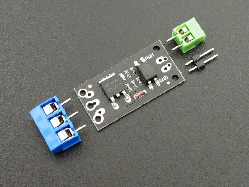
FemtoFET™ N-Channel MOSFET transistors are the smallest, low on-resistance Power MOSFETs available in the marketplace today. The FemtoFET is Land Grid Array (LGA) package, which is a silicon Chip Scale Package with metal pads instead of solder balls. 2N7000 is a small signal N-channel MOSFET. MOSFETs are power electronic switches just like transistors, but with a higher current and voltage rating.
- MOSFETs are in stock with same-day shipping at Mouser Electronics from industry leading manufacturers.Mouser is an authorized distributor for many MOSFET manufacturers including Diodes Inc., Infineon, IXYS, Microchip, Nexperia, ON Semiconductor, STMicroelectronics, Texas.
- Hybrid-Pi and T-model for the MOSFET transistor. Expressions for the small model parameters (gm and ro).
- 200mA, 60V, N-Channel Small Signal MOSFET - Enhancement. 200mA, 60V, N-Channel MOSFET - Enahncement.
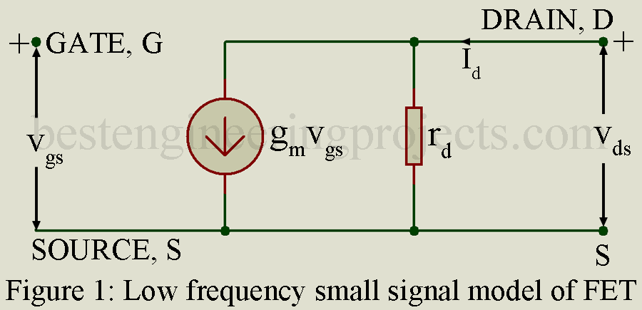
Figure 1 shows the MOSFET amplifier at the small-signal interpretation.
a El secreto mas raro earl nightingale pdf.
b
Figure 1.The MOSFET amplifier and it’s small-signal model.

This non-linearity significantly complicates design development, so linearity of the amplifier is more interesting from the designer point of view. Small-signal approximation states that at small time-varying incremental amplification, the time-changing component will be linear. Figure 2 depicts the transfer characteristics with small-signal interpretation. In this situation the incremental transconductance is , where g is the ratio between input voltage and current. Small-signal gain is .


Figure 2. The transfer function for the MOSFET amplifier.
In order to calculate the incremental small-signal response, we have to do a few calculations: we need to find the large-signal response for the certain DC operating point of the signal. And then we must use the Taylor approximation to obtain the small-signal response for this operating point.
Considering the circuit in terms of small-signal approximation we must:
1. Put all components to their operating value.
2. Linearise the behaviour of every circuit component at the operating point.
3. Replace orginal circuit components with their linearised components.
Some handbooks give the extensive explanation of the small-signal approximation of different components of circuits like DC voltage and current sources. In general, we need to find the small-signal approximation of the circuit component so it’small signal deviation for this component is at some specific value for the operation point .
For the MOSFET amplifier, small-signal approximation for the operating current is , and . Figure 3 depicts the amplifier and its small-signal model.

a
b
Figure 3. The difference amplifier and its small signal model.
Small Signal Model Of Mosfet
The input resistance for this model will be , the output resistance is . The current gain for this model will be . Power gain for this scheme will be .
Let’s consider the difference amplifier AD8479 for high quality amplification. This difference amplifier consists of the operational amplifier and resistor network. The output of the difference amplifier , where is the difference-mode gain, and is the common-mode gain. These can lead us to the common mode rejection ratio for the amplifier .[1]
Figure 4. Functional diagram for the difference amplifier AD8479, Analog Devices. [2]
Mosfet Transconductance

Small Signal E.mosfet
[1] “Foundations of Analog and Digital Electronic Circuits”, Anant Agarwal and J. H. Lang, Elsevier.
Mosfet Small Signal Analysis Example
[2] AD8479 datasheet, Analog Devices.
